Thursday, 25 October 2012

Crankshaft Main Bearings - Remove and Install


Removal Procedure

Remove:
- the engine oil pump.
- the crankshaft rear seal. Ensure that the main bearing cap is marked for the correct location and orientation.


- the two setscrews (1) and the main bearing cap (2) from the cylinder block.


- the lower main bearing shell (3) from the main bearing cap (2). Keep the main bearing shell and the main bearing cap together. The lower main bearing shell is a plain bearing that has no oil holes.


For number six main bearing, remove the two thrust washers (4) from the cylinder block. In order to remove the thrust washers (4), use Tooling to rotate the crankshaft in the correct direction. If necessary, push the crankshaft toward the front of the engine or push the crankshaft toward the rear of the engine while you rotate the crankshaft, in order to aid removal. The thrust washers have a locating tab at one end.
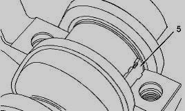

Push out the upper main bearing shell (5) with a suitable tool from the side opposite the locating tab. Carefully rotate the crankshaft while you push on the bearing shell.
- the upper main bearing shell (5) from the cylinder block. Keep the bearing shells together. The upper main bearing shell has a groove and two oil holes.

Installation Procedure

Ensure that the main bearing shells are clean and free from wear or damage. If necessary, replace the main bearing shells. Clean the journals of the crankshaft. Inspect the journals of the crankshaft for damage. If necessary, replace the crankshaft or recondition the crankshaft.
Lubricate the crankshaft journal and the upper main bearing shell (5) with clean engine oil. Slide the upper main bearing shell (5) into position between the crankshaft journal and the cylinder block. Ensure that the locating tab for the upper main bearing shell is correctly seated in the slot in the cylinder block. The upper main bearing shell has a groove and two oil holes.

For number six main bearing, ensure that the two thrust washers (4) are clean and free from wear or damage. If necessary, replace the thrust washers. Lubricate the thrust washers (4) with clean engine oil. Slide the thrust washers (4) into position between the crankshaft and the cylinder block. Ensure that the locating tab is correctly seated in the cylinder block.
Install:
- the lower main bearing shell (3) into the main bearing cap (2). Ensure that the locating tab for the lower main bearing shell is correctly seated into the slot in the bearing cap. The lower main bearing shell is a plain bearing that has no oil holes.


Lubricate the crankshaft journal and the lower main bearing shell with clean engine oil. Install the main bearing cap (2) to the cylinder block. Ensure the correct orientation of the main bearing cap. The locating tab for the upper and the lower bearing should be on the same side of the engine. Lubricate the threads of the setscrews (1) with clean engine oil. Lubricate the underside of the heads of the setscrews (1) with clean engine oil.
Install the setscrews (1) to the main bearing cap (2). Evenly tighten the setscrews in order to pull the cap (2) into position. Ensure that the cap is correctly seated. Do not tap the main bearing cap into position as the bearing shell may be dislodged. Tighten the setscrews (1) to a torque of 80 N�m (59 lb ft). Turn the setscrews (1) through an additional 90 degrees. Use Tooling to achieve the correct final torque.

Check the crankshaft end play. Push the crankshaft toward the front of the engine.
- Tooling to the cylinder block and the rear face of the crankshaft. Push the crankshaft toward the rear of the engine. Use Tooling to measure the crankshaft end play. The permissible crankshaft end play is 0.17 mm (0.007 inch) to 0.41 mm (0.016 inch).
- the crankshaft rear seal.
- the engine oil pump. 

Tuesday, 23 October 2012

Connecting Rod Bearings � Remove and Install


Removal Procedure

Remove the engine oil pump. Use Tooling to rotate the crankshaft until the crank pin is at the bottom center position.


The connecting rod and the connecting rod cap should have an etched number (X) on the side. The number on the connecting rod and the connecting rod cap must match. If necessary, make a temporary mark on the connecting rod (5) and the connecting rod cap (2) in order to identify the cylinder number. Do not punch identification marks onto fracture split connecting rods. Do not stamp identification marks onto fracture split connecting rods. Remove the two setscrews (1) and the connecting rod cap (2) from the connecting rod (5). Discard the setscrews (1). Remove the lower bearing shell (3) from the connecting rod cap (2). Keep the bearing shell and the connecting rod cap together.


Carefully push the connecting rod (5) into the cylinder bore until the connecting rod (5) is clear of the crankshaft. Remove the upper bearing shell (4) from the connecting rod. Keep the bearing shells together. Do not push on the fracture split surfaces of the connecting rod as damage may result. Do not allow the connecting rod to contact the piston cooling jet. Repeat Steps for the remaining bearing shells. Fracture split connecting rods should not be left without the connecting rod caps installed.

Installation Procedure

Inspect the pins of the crankshaft for damage. If the crankshaft is damaged, replace the crankshaft. Install:
- the upper bearing shell (4) into the connecting rod (5). Ensure that the locating tab for the upper bearing shell is correctly seated in the slot in the connecting rod. The ends of the upper bearing shell must be centered in the connecting rod. The ends of the upper bearing shell must be equally positioned in relation to the mating faces of the connecting rod. Lubricate the upper bearing shell (4) with clean engine oil. Use Tooling to rotate the crankshaft until the crankshaft pin is at the bottom dead center position. Carefully pull the connecting rod (5) against the crankshaft pin. Do not allow the connecting rod to contact the piston cooling jet. Clean connecting rod cap (2).
- the lower bearing shell (3) into the connecting rod cap (2). Ensure that the locating tab for the lower bearing shell is correctly seated in the slot in the connecting rod cap. The ends of the lower bearing shell must be centered in the connecting rod cap. The ends of the lower bearing shell must be equally positioned in relation to the mating faces of the connecting rod cap. Lubricate the pin of the crankshaft and lubricate the lower bearing shell (3) with clean engine oil.
- the connecting rod cap (2) to the connecting rod (5). Ensure that the etched number (X) on connecting rod cap (2) matches the etched number (X) on connecting rod (5). Ensure the correct orientation of the connecting rod cap. The locating tab for the upper bearing shell and the lower bearing shell should be on the same side.
- two new setscrews (1) to the connecting rod. Tighten the setscrews evenly to a torque of 18 N�m (13 lb ft). Do not reuse the old setscrews in order to secure the connecting rod cap. Tighten the setscrews evenly to a torque of 70 N�m (52 lb ft). Turn the setscrews through an additional 120 degrees. Use Tooling to achieve the correct final torque. Ensure that the installed connecting rod assembly has tactile side play. Rotate the crankshaft in order to ensure that there is no binding. Repeat Steps for the remaining connecting rod bearings.
- the engine oil pump.

Sunday, 21 October 2012

Reassembling the Dyna VT power take-off - Installing the set of discs on the disc carrier


PTO clutch


PTO clutch parts
1 Shim
2 Taper roller bearings
3 Clutch cover
4 Cylindrical screw
5 Shim
6 Internal blade holder
8 Shim
9 Spring washer
10 Set of blades
11 Disc
12 Intermediate plate
13 Piston
14 Ring
16 Lip seal
18 Plate
19 Lip seal
20 Brake disc
21 Allen screw
22 Grower washer
23 Bush
25 Pinion
28 Taper roller bearing
29 Nozzle
30 Locking half-rings
31 Circlip
32 O�ring
35 Shaft
36 Taper roller bearing
37 Ring with rectangular section
38 Grub screw
39 Nozzle
40 Sensor
42 Shaft

Rear PTO drive


Rear PTO drive parts
101 Taper roller bearing
102 Shim
104 Clutch body
105 Roller
107 Circlip
108 Washer
109 Needle bearing cage
110 Spacer
112 Circlip
113 Taper roller bearing
114 Circlip
115 Allen screw
116 Stop
118 Pinion (1000 rpm)
118A Pinion (540 or 750 rpm)
120 Shaft
121 Circlip
122 Washer
123 Taper roller bearing
124 Shim
125 Grub screw
126 Spi seal
127 O�ring
128 Bearing cover
129 Cylindrical screw
132 Spacer
133 Threaded stud M10 x 50 - 10.9
134 Nut M10-10
135 PTO guard
137 End-fitting
139 Sensor
140 Allen screw


Start with an external blade. Next alternate with an internal blade (11). Each internal blade (11) should be fitted in respect to the narrow slot (pos. 2) while the wide slot (pos. 3) should be positioned either side alternately. Total number of discs: 7 external discs (12) and 6 internal discs (11).


Fit the disc carrier (6) together with the set of Belleville washers (9). Fit the compression tool (ref. X 899 980 145). Compress the clutch. Fit the locking half-rings (30). If the locking half-rings are chamfered on just one side, the chamfered side must face the disc carrier (6). If the disc carrier (6) does not fit into place, fit it without the set of discs (10) and mark the teeth. Push the set of discs home, ensuring it is correctly centred. Measure the distance (uncoupling clearance) using laminated shims. Specified values: 1.75 to 3.50 mm. If the minimum distance of 1.75 mm is not obtained, the discs are wrapped. Fit a new set of discs (10).
Smear the thread of the nozzle (29) with plastic binder (ref. X 903 050 084).
Tighten the nozzle (29) to a torque of:25 Nm. If necessary, fit the bearing (28) to its stop with its closed part facing upwards into the interior of the
clutch cover (3). Fit the bearing (2) up against the clutch cover (3). Adjust the position of the external discs (12) and fit the clutch cover (3) to its stop.
Fit compensating shims (1) on the bearing (2).
Measure and note the distance between the mating faces. For example: 178.6 mm. The distance between the flange face and the mating face of the journal is written in white on the top part of the rear axle housing. Example: 178.71. The distance between the journal of the bearing (2) and the flange face of the housing cover should be less than 0.1 to 0.2 mm, as the written value indicates.
This means that the journal clearance must be 0.1 to 0.2 mm. If not, correct it with compensating shims (1). The distance between the flange face and the mating face of the journal of the lower shaft is written in white on the lower part of the rear axle housing. Example: 148.75. This value is not necessary in case of repair, because a dial gauge must be used to measure the bearing clearance. Check the bearing clearance of the lower shaft (120). Fit the compensating shims (1) in the upper bore. Smear 4 new O�rings with miscible grease and fit them at the position of the oil pressure pipes.


Clean the housing mating face. Check the 2 locating pins are fitted correctly.


Smear the mating face with sealing product (ref. X903.050.074). Carefully raise the housing cover and fit it on the rear axle housing. Tighten the M18 screws and nuts to a torque of: 400 Nm. If necessary:
Smear the outside of a new shaft sealing ring (126) with a thin layer of sealing product (ref. X 903.051.711), and insert it until it comes into light contact with the cover (128), the seal lips turned towards the oil chamber. Depth approximately 5 mm. Fill the lip seals 2/3 full with miscible grease.
Fit the corresponding compensating shims (124). Smear new O�rings (127) with miscible grease and fit them in the groove of the cover (128). Smear the thread of the screws (129) with plastic binder (ref. X 903.050.084) and tighten. Rotate the shaft (120) 10 times. Fit a dial gauge. Push in the shaft (120) once and note the clearance value J2.


Rotate the shaft (120) 10 times. Fit a dial gauge. Pull once on the shaft (120) and note the clearance value J1.
Total clearance J = J1+ J2. 0.02 mm < J < 0.07 mm
If not, correct it with compensating shims (124). PTO end-fitting with 6 x 1� 3/8" splines Also compatible:
PTO end-fitting with 21 x 1� 3/8" splines
PTO end-fitting with 6 x 1� 3/4" splines
PTO end-fitting with 20 x 1� 3/4" splines


The PTO end-fitting has 4 drive holes for the PTO sensorFit the end-fitting (137). Fit the spacer (132).


Lock the end-fitting (137 with a screw M16 (for easier assembly). Tighten the nuts (134) (M0-10) to a torque of: 69 Nm. Top up the transmission oil level.

Reassembling the Dyna VT power take-off


PTO clutch


PTO clutch parts
1 Shim
2 Taper roller bearings
3 Clutch cover
4 Cylindrical screw
5 Shim
6 Internal blade holder
8 Shim
9 Spring washer
10 Set of blades
11 Disc
12 Intermediate plate
13 Piston
14 Ring
16 Lip seal
18 Plate
19 Lip seal
20 Brake disc
21 Allen screw
22 Grower washer
23 Bush
25 Pinion
28 Taper roller bearing
29 Nozzle
30 Locking half-rings
31 Circlip
32 O�ring
35 Shaft
36 Taper roller bearing
37 Ring with rectangular section
38 Grub screw
39 Nozzle
40 Sensor
42 Shaft

Rear PTO drive


Rear PTO drive parts
101 Taper roller bearing
102 Shim
104 Clutch body
105 Roller
107 Circlip
108 Washer
109 Needle bearing cage
110 Spacer
112 Circlip
113 Taper roller bearing
114 Circlip
115 Allen screw
116 Stop
118 Pinion (1000 rpm)
118A Pinion (540 or 750 rpm)
120 Shaft
121 Circlip
122 Washer
123 Taper roller bearing
124 Shim
125 Grub screw
126 Spi seal
127 O�ring
128 Bearing cover
129 Cylindrical screw
132 Spacer
133 Threaded stud M10 x 50 - 10.9
134 Nut M10-10
135 PTO guard
137 End-fitting
139 Sensor
140 Allen screw


Rear PTO control


Rear PTO control parts
201 Stirrup
202 Hexagonal nut
203 Stud
205 Allen screw
206 Hexagonal nut
207 Spacer pipe
210 Hexagonal nut
211 Hexagonal nut
212 Washer
213 Hexagonal nut
214 Roller
216 Allen screw
217 Rams
218 O�ring
219 Compact seal
220 Compact seal
221 Spring
222 Piston
224 Piston
225 Allen screw
226 Rams
226 Rams


Rear PTO cover


Rear PTO cover parts
301 Rear axle housing
303 Seal
304 Cover
305 Allen screw
307 Closing plug
308 Sealing ring
309 Closing plug
310 Sealing ring
311 Closing plug
315 Dowel pin
316 Housing cover
317 Screw M18 x 90 - 10.9
318 Screw M18 x 110 -10.9
319 Threaded stud M18 x 130 - 10.9
322 Sealing ring
325 Cylindrical screw


Fit home the bearing (113) in the pinion (118a) and lock with the circlip (114), then fit the pinion (118) to its stop. Fit the circlip (112) on the opposite side.
Fit home the internal ring of the bearing (123) on the shaft (120).
Position the washer (122). Fit the circlip (121). Smear the 2 grub screws (25) with plastic binder (ref. X 903.050.084) and tighten them until the internal ring of the bearing (123) reaches its stop. The washer (122) must be fitted home. Fit the 1st needle bearing cage (109), the spacer (110) and the 2nd needle bearing cage (109) on the shaft (120). Fit the shaft (120). Position the washer (108). Fit the circlip (107). Fit new seals (219) in the ram (217).
Fit a new O�ring (218) in the groove of the ram (217). Smear the oil tight seals with miscible grease. Insert the piston (222) and spring (221) as indicated in the ram (217). The oil tight seal (219) is comprised of 2 parts: an O�ring on the outside and a piston strip guide on the inside.
Fit new seals (220) in the ram (226). Fit a new O�ring (218) in the groove of the ram (226). Smear the oil tight seals with miscible grease.
Insert the piston (224) and spring (221) as indicated in the ram (226). The oil tight seal (219) is comprised of 2 parts: an O�ring on the outside and a piston strip guide on the inside. Fit the rams (217 and 226). Smear the thread of the screws (216 and 225) with plastic binder (ref. X 903.050.084) and tighten the
screws to the following torque: 49 Nm
Refit the hydraulic pipes which have been removed in the housing cover (316).
If the housing is fitted with a new cover (316), screw the nozzle (29) to its stop in the threaded bore. Fit home the external ring of the bearing (36).
Smear 2 new rings (37) with miscible grease and install and lock them in the grooves of the shaft (35). Fit home the internal ring of the bearing (36).
When assembling a new shaft (35), smear the thread of the threaded stud (38) with plastic binder (ref. X 903.050.084), and screw to its stop. Tighten the nozzle (29) to its stop. Fit the pre-assembled shaft (35) in the housing cover (316). If required, fit compensating shims (124) and fit home the external ring of the bearing (123). Fit the pair of ring gears and the pinion (25).

Pre-assembling the stirrup

Smear the thread of the screws (205) with plastic binder (ref. X 903 050 084).
Fit spacers (207) and rollers (214). Tighten nuts (206). Insert the rollers (105) into the clutch body (104). Smear the thread of the screws (203) with plastic binder (ref. X 903 050 084). Fit the stirrup tight to an identical distance, then loosen each screw (203) by 1/6 of a turn and lock them in this position.
Screw the nuts (ref. 210, 211 and 213) onto the rods of the pistons (222, 224). Fit the washers (212) with their chamfer turned upwards. Fit the pre-assembled stirrup (201). Fit the washers (212) with their chamfer turned downwards. Unscrew the nuts (210 and 211). Smear the thread of the screws (115) with plastic binder (ref. X 903 050 084). Fit the stops (116) and lock the screws (115). The following must be carried out before setting stirrup travel:
The oblong hole in the stirrup (201) must be turned towards the ram (226).
Screw and lock the nuts (211, 210) to their stop. Screw a locally made eye nut M12 onto the piston rod of the ram (217). Using a lifting tool, pull hard
on the piston rod. (Coupling at 750 or 540 rpm). Check the clearance of the clutch body (104). Specified value: 0.1 to 0.2 mm clearance. If outside the specified clearance:
Adjust with nuts M12 (top and bottom) until clearance of 0.1 to 0.2 mm is obtained. Take off the lifting tool and unscrew the eye nut M12.
Push the piston rod of the ram (226) fully in using a clamp, until the nuts (213) and at their stop. (Lifting limit, 1000 rpm position).
Check the clearance of the clutch body (104). Specified value: 0.1 to 0.2 mm clearance. If outside the specified clearance:
Adjust the nuts (213) until clearance of 0.1 to 0.2 mm is obtained.
Take off the clamp. The coupling shifts to "Neutral" position. The 750 or 540 and 1000 rpm ring gears should be able to turn freely. The upward and downward free travel of the coupling should be identical. If not, readjust the coupling. Fit the shim (102). Fit the internal ring of the bearing (101) up against the shaft (120). Fit the pinion (25). Smear a new O�ring with miscible grease and fit it in the groove of the shaft (35). Check the brake disc (20) for wear. If necessary, fit a new brake disc (20). Fit the circlip (31).
Smear a new lip seal (19) with miscible grease and fit it in the brake disc groove, with the seal lips turned towards the oil chamber. Fit the blade (18).
Smear the thread of the screw (21) with Loctite (ref. X 903 054 084), and fit the Grower washer (22) and socket (23). Tighten the screw.
Smear a new lip seal (16) with miscible grease and fit it in the inner groove of the piston, with the seal lips turned towards the oil chamber. Fit the pre-assembled piston (13). Fit the ring (14). Fit 5 Belleville washers (9) with the large external diameters facing each other, and the compensating shims (8). The external diameter of the first Belleville washer (9) should be turned towards the ring (14) of the piston (13). If required, for example if compensating shims (8) are lost, set the preload of the Belleville washer set (9).

Setting the preload of Belleville washer set

Remove the shim (5) from the internal disc carrier (6).
Smear the thread of the screw (4) with plastic binder (Ref. X 903 050 084) and tighten. Fit home the pre-assembled ring carrier (6).
Measure and note the distance between the disc carrier (6) and the end of the shaft (35). Example: 23.2 mm.
Fit the compression tool (ref. X 899 980 145) and compress the set of Belleville washers (9). Fit the locking half-rings (30).
If the locking half-rings (30) are chamfered on just one side, the chamfered side must face the disc carrier (6). Remove the compression tool (ref. X 899 980 145) Measure and note the distance between the disc carrier (6) and the end of the shaft (35). Example: 25.8 mm. If the washer set gives compensating clearance of approximately 2.5 mm when completely compressed, the preload is correct. If not, correct it with compensating shims.

Saturday, 20 October 2012

Dyna VT Transmission - Disassembling the rear PTO


PTO clutch


PTO clutch parts
1 Shim
2 Taper roller bearings
3 Clutch cover
4 Cylindrical screw
5 Shim
6 Internal blade holder
8 Shim
9 Spring washer
10 Set of blades
11 Disc
12 Intermediate plate
13 Piston
14 Ring
16 Lip seal
18 Plate
19 Lip seal
20 Brake disc
21 Allen screw
22 Grower washer
23 Bush
25 Pinion
28 Taper roller bearing
29 Nozzle
30 Locking half-rings
31 Circlip
32 O�ring
35 Shaft
36 Taper roller bearing
37 Ring with rectangular section
38 Grub screw
39 Nozzle
40 Sensor
42 Shaft

Rear PTO drive


Rear PTO drive parts
101 Taper roller bearing
102 Shim
104 Clutch body
105 Roller
107 Circlip
108 Washer
109 Needle bearing cage
110 Spacer
112 Circlip
113 Taper roller bearing
114 Circlip
115 Allen screw
116 Stop
118 Pinion (1000 rpm)
118A Pinion (540 or 750 rpm)
120 Shaft
121 Circlip
122 Washer
123 Taper roller bearing
124 Shim
125 Grub screw
126 Spi seal
127 O�ring
128 Bearing cover
129 Cylindrical screw
132 Spacer
133 Threaded stud M10 x 50 - 10.9
134 Nut M10-10
135 PTO guard
137 End-fitting
139 Sensor
140 Allen screw


Rear PTO control


Rear PTO control parts
201 Stirrup
202 Hexagonal nut
203 Stud
205 Allen screw
206 Hexagonal nut
207 Spacer pipe
210 Hexagonal nut
211 Hexagonal nut
212 Washer
213 Hexagonal nut
214 Roller
216 Allen screw
217 Rams
218 O�ring
219 Compact seal
220 Compact seal
221 Spring
222 Piston
224 Piston
225 Allen screw
226 Rams

226 Rams

Disassembling the power take-off (Dyna VT)

Lower the rear linkage. Drain the transmission oil. Remove the trailer linkage (depending on equipment). Mark and remove the PTO connector TR9


Mark and remove the PTO connector TR10Unscrew all attachment screws. Take the silicone out of the threaded bores and tighten 2 screws M12 Support the cover using a lifting tool and push it back using the two screws.


Take off the rear PTO transmission cover. Take care of the adjustment shims, which are used to adjust the bearing clearance. Push back the clutch cover (3) using 2 disc screws M10. Remove the nozzle (29). Fit the compression tool (ref. X899.980.145) and compress the clutch. Extract the locking half-rings (30).

Release the clutch. Remove the disc carrier and the set of discs (10). Remove the adjustment shims (8), the set of Belleville washers (9) and the ring (14). Remove the piston (13). Remove a screws (21) and take off the blade (18). Take off the circlip (31) and remove the brake disc (20). Take off the brake disc. Extract the bearing (101) using an extractor. Take out the washer. Unscrew the nuts (210 and 211). Note the values of the nuts (210 and 211) if required. Remove the stops (116). Take out the control mechanism. Remove the pinions (118) and (118a).

Take out the shaft (35). If required, take off the external rings of the bearing. If necessary, remove the ram (217) and / or (226). Take off the circlip (107), washer (108) and pinions. Remove the circlip (112). Release the pinion (118).