Sunday, 21 October 2012

Reassembling the Dyna VT power take-off


PTO clutch


PTO clutch parts
1 Shim
2 Taper roller bearings
3 Clutch cover
4 Cylindrical screw
5 Shim
6 Internal blade holder
8 Shim
9 Spring washer
10 Set of blades
11 Disc
12 Intermediate plate
13 Piston
14 Ring
16 Lip seal
18 Plate
19 Lip seal
20 Brake disc
21 Allen screw
22 Grower washer
23 Bush
25 Pinion
28 Taper roller bearing
29 Nozzle
30 Locking half-rings
31 Circlip
32 O�ring
35 Shaft
36 Taper roller bearing
37 Ring with rectangular section
38 Grub screw
39 Nozzle
40 Sensor
42 Shaft

Rear PTO drive


Rear PTO drive parts
101 Taper roller bearing
102 Shim
104 Clutch body
105 Roller
107 Circlip
108 Washer
109 Needle bearing cage
110 Spacer
112 Circlip
113 Taper roller bearing
114 Circlip
115 Allen screw
116 Stop
118 Pinion (1000 rpm)
118A Pinion (540 or 750 rpm)
120 Shaft
121 Circlip
122 Washer
123 Taper roller bearing
124 Shim
125 Grub screw
126 Spi seal
127 O�ring
128 Bearing cover
129 Cylindrical screw
132 Spacer
133 Threaded stud M10 x 50 - 10.9
134 Nut M10-10
135 PTO guard
137 End-fitting
139 Sensor
140 Allen screw


Rear PTO control


Rear PTO control parts
201 Stirrup
202 Hexagonal nut
203 Stud
205 Allen screw
206 Hexagonal nut
207 Spacer pipe
210 Hexagonal nut
211 Hexagonal nut
212 Washer
213 Hexagonal nut
214 Roller
216 Allen screw
217 Rams
218 O�ring
219 Compact seal
220 Compact seal
221 Spring
222 Piston
224 Piston
225 Allen screw
226 Rams
226 Rams


Rear PTO cover


Rear PTO cover parts
301 Rear axle housing
303 Seal
304 Cover
305 Allen screw
307 Closing plug
308 Sealing ring
309 Closing plug
310 Sealing ring
311 Closing plug
315 Dowel pin
316 Housing cover
317 Screw M18 x 90 - 10.9
318 Screw M18 x 110 -10.9
319 Threaded stud M18 x 130 - 10.9
322 Sealing ring
325 Cylindrical screw


Fit home the bearing (113) in the pinion (118a) and lock with the circlip (114), then fit the pinion (118) to its stop. Fit the circlip (112) on the opposite side.
Fit home the internal ring of the bearing (123) on the shaft (120).
Position the washer (122). Fit the circlip (121). Smear the 2 grub screws (25) with plastic binder (ref. X 903.050.084) and tighten them until the internal ring of the bearing (123) reaches its stop. The washer (122) must be fitted home. Fit the 1st needle bearing cage (109), the spacer (110) and the 2nd needle bearing cage (109) on the shaft (120). Fit the shaft (120). Position the washer (108). Fit the circlip (107). Fit new seals (219) in the ram (217).
Fit a new O�ring (218) in the groove of the ram (217). Smear the oil tight seals with miscible grease. Insert the piston (222) and spring (221) as indicated in the ram (217). The oil tight seal (219) is comprised of 2 parts: an O�ring on the outside and a piston strip guide on the inside.
Fit new seals (220) in the ram (226). Fit a new O�ring (218) in the groove of the ram (226). Smear the oil tight seals with miscible grease.
Insert the piston (224) and spring (221) as indicated in the ram (226). The oil tight seal (219) is comprised of 2 parts: an O�ring on the outside and a piston strip guide on the inside. Fit the rams (217 and 226). Smear the thread of the screws (216 and 225) with plastic binder (ref. X 903.050.084) and tighten the
screws to the following torque: 49 Nm
Refit the hydraulic pipes which have been removed in the housing cover (316).
If the housing is fitted with a new cover (316), screw the nozzle (29) to its stop in the threaded bore. Fit home the external ring of the bearing (36).
Smear 2 new rings (37) with miscible grease and install and lock them in the grooves of the shaft (35). Fit home the internal ring of the bearing (36).
When assembling a new shaft (35), smear the thread of the threaded stud (38) with plastic binder (ref. X 903.050.084), and screw to its stop. Tighten the nozzle (29) to its stop. Fit the pre-assembled shaft (35) in the housing cover (316). If required, fit compensating shims (124) and fit home the external ring of the bearing (123). Fit the pair of ring gears and the pinion (25).

Pre-assembling the stirrup

Smear the thread of the screws (205) with plastic binder (ref. X 903 050 084).
Fit spacers (207) and rollers (214). Tighten nuts (206). Insert the rollers (105) into the clutch body (104). Smear the thread of the screws (203) with plastic binder (ref. X 903 050 084). Fit the stirrup tight to an identical distance, then loosen each screw (203) by 1/6 of a turn and lock them in this position.
Screw the nuts (ref. 210, 211 and 213) onto the rods of the pistons (222, 224). Fit the washers (212) with their chamfer turned upwards. Fit the pre-assembled stirrup (201). Fit the washers (212) with their chamfer turned downwards. Unscrew the nuts (210 and 211). Smear the thread of the screws (115) with plastic binder (ref. X 903 050 084). Fit the stops (116) and lock the screws (115). The following must be carried out before setting stirrup travel:
The oblong hole in the stirrup (201) must be turned towards the ram (226).
Screw and lock the nuts (211, 210) to their stop. Screw a locally made eye nut M12 onto the piston rod of the ram (217). Using a lifting tool, pull hard
on the piston rod. (Coupling at 750 or 540 rpm). Check the clearance of the clutch body (104). Specified value: 0.1 to 0.2 mm clearance. If outside the specified clearance:
Adjust with nuts M12 (top and bottom) until clearance of 0.1 to 0.2 mm is obtained. Take off the lifting tool and unscrew the eye nut M12.
Push the piston rod of the ram (226) fully in using a clamp, until the nuts (213) and at their stop. (Lifting limit, 1000 rpm position).
Check the clearance of the clutch body (104). Specified value: 0.1 to 0.2 mm clearance. If outside the specified clearance:
Adjust the nuts (213) until clearance of 0.1 to 0.2 mm is obtained.
Take off the clamp. The coupling shifts to "Neutral" position. The 750 or 540 and 1000 rpm ring gears should be able to turn freely. The upward and downward free travel of the coupling should be identical. If not, readjust the coupling. Fit the shim (102). Fit the internal ring of the bearing (101) up against the shaft (120). Fit the pinion (25). Smear a new O�ring with miscible grease and fit it in the groove of the shaft (35). Check the brake disc (20) for wear. If necessary, fit a new brake disc (20). Fit the circlip (31).
Smear a new lip seal (19) with miscible grease and fit it in the brake disc groove, with the seal lips turned towards the oil chamber. Fit the blade (18).
Smear the thread of the screw (21) with Loctite (ref. X 903 054 084), and fit the Grower washer (22) and socket (23). Tighten the screw.
Smear a new lip seal (16) with miscible grease and fit it in the inner groove of the piston, with the seal lips turned towards the oil chamber. Fit the pre-assembled piston (13). Fit the ring (14). Fit 5 Belleville washers (9) with the large external diameters facing each other, and the compensating shims (8). The external diameter of the first Belleville washer (9) should be turned towards the ring (14) of the piston (13). If required, for example if compensating shims (8) are lost, set the preload of the Belleville washer set (9).

Setting the preload of Belleville washer set

Remove the shim (5) from the internal disc carrier (6).
Smear the thread of the screw (4) with plastic binder (Ref. X 903 050 084) and tighten. Fit home the pre-assembled ring carrier (6).
Measure and note the distance between the disc carrier (6) and the end of the shaft (35). Example: 23.2 mm.
Fit the compression tool (ref. X 899 980 145) and compress the set of Belleville washers (9). Fit the locking half-rings (30).
If the locking half-rings (30) are chamfered on just one side, the chamfered side must face the disc carrier (6). Remove the compression tool (ref. X 899 980 145) Measure and note the distance between the disc carrier (6) and the end of the shaft (35). Example: 25.8 mm. If the washer set gives compensating clearance of approximately 2.5 mm when completely compressed, the preload is correct. If not, correct it with compensating shims.

Saturday, 20 October 2012

Dyna VT Transmission - Disassembling the rear PTO


PTO clutch


PTO clutch parts
1 Shim
2 Taper roller bearings
3 Clutch cover
4 Cylindrical screw
5 Shim
6 Internal blade holder
8 Shim
9 Spring washer
10 Set of blades
11 Disc
12 Intermediate plate
13 Piston
14 Ring
16 Lip seal
18 Plate
19 Lip seal
20 Brake disc
21 Allen screw
22 Grower washer
23 Bush
25 Pinion
28 Taper roller bearing
29 Nozzle
30 Locking half-rings
31 Circlip
32 O�ring
35 Shaft
36 Taper roller bearing
37 Ring with rectangular section
38 Grub screw
39 Nozzle
40 Sensor
42 Shaft

Rear PTO drive


Rear PTO drive parts
101 Taper roller bearing
102 Shim
104 Clutch body
105 Roller
107 Circlip
108 Washer
109 Needle bearing cage
110 Spacer
112 Circlip
113 Taper roller bearing
114 Circlip
115 Allen screw
116 Stop
118 Pinion (1000 rpm)
118A Pinion (540 or 750 rpm)
120 Shaft
121 Circlip
122 Washer
123 Taper roller bearing
124 Shim
125 Grub screw
126 Spi seal
127 O�ring
128 Bearing cover
129 Cylindrical screw
132 Spacer
133 Threaded stud M10 x 50 - 10.9
134 Nut M10-10
135 PTO guard
137 End-fitting
139 Sensor
140 Allen screw


Rear PTO control


Rear PTO control parts
201 Stirrup
202 Hexagonal nut
203 Stud
205 Allen screw
206 Hexagonal nut
207 Spacer pipe
210 Hexagonal nut
211 Hexagonal nut
212 Washer
213 Hexagonal nut
214 Roller
216 Allen screw
217 Rams
218 O�ring
219 Compact seal
220 Compact seal
221 Spring
222 Piston
224 Piston
225 Allen screw
226 Rams

226 Rams

Disassembling the power take-off (Dyna VT)

Lower the rear linkage. Drain the transmission oil. Remove the trailer linkage (depending on equipment). Mark and remove the PTO connector TR9. 


Mark and remove the PTO connector TR10. Unscrew all attachment screws. Take the silicone out of the threaded bores and tighten 2 screws M12 Support the cover using a lifting tool and push it back using the two screws.


Take off the rear PTO transmission cover. Take care of the adjustment shims, which are used to adjust the bearing clearance. Push back the clutch cover (3) using 2 disc screws M10. Remove the nozzle (29). Fit the compression tool (ref. X899.980.145) and compress the clutch. Extract the locking half-rings (30).

Release the clutch. Remove the disc carrier and the set of discs (10). Remove the adjustment shims (8), the set of Belleville washers (9) and the ring (14). Remove the piston (13). Remove a screws (21) and take off the blade (18). Take off the circlip (31) and remove the brake disc (20). Take off the brake disc. Extract the bearing (101) using an extractor. Take out the washer. Unscrew the nuts (210 and 211). Note the values of the nuts (210 and 211) if required. Remove the stops (116). Take out the control mechanism. Remove the pinions (118) and (118a).

Take out the shaft (35). If required, take off the external rings of the bearing. If necessary, remove the ram (217) and / or (226). Take off the circlip (107), washer (108) and pinions. Remove the circlip (112). Release the pinion (118).

Friday, 19 October 2012

DYNA VT transmission � hydraulic


Forward / Reverse high pressure relief valves

The purpose of the high pressure relief valves is to regulate the increase in HP pressure. They protect the transmission elements (hydrostatic motors and pump).


A = Coupler and clutch functions inactive: Pressure identical in both chambers. The spool is held in closed position by the spring.
B = Coupler and clutch functions active: the pressure drop caused by the restrictor (nozzle) applies a force to the spool that is more powerful than the force of the spring. The spool moves to the right, bringing PH into contact with ES (booster).
C = HP pressure is limited by the clutch and coupler spools.
Replacing Forward / Reverse HP pressure relief valves
Drain the transmission oil


Loosen the 2 plugs with hexagonal heads located under the transmission housing. Use a wrench to remove the high pressure relief valves.
V = Forward high pressure relief valve
R = Reverse high pressure relief valve.


The high pressure relief valve is a controlled pressure relief valve.
Adjustment pressure when new: R500 + 20 bar.
Adjustment pressure after several hours: 480 � 20 bar.
Only replace O�rings if they are damaged. Do not move the thrust collar. Tighten the pressure relief valve to a torque of 250 + 20 Nm

Scavenging valve

This valve allows to �flush� the oil in the hydrostatic loop.


Operation 
Pressure in A, B: max. 500 bar.
Pressure in T: max. 50 bar
Opening pressure: delta p = 7 bar between A and B


Transmission at neutral 
pA = pB, delta p < 7 bar
The spool is held in �middle� position by the spring.
The two channels (A, B) are closed.


�Pulling� phase 
pA > pB, delta p > 7 bar
The spool moves upwards via control port XA.
Channel B communicates with T. The hot oil coming from the low pressure side B can therefore be
�flushed� and sent by the cooler via port T.


�Pushing� phase 
pA > pB, delta p > 7 bar
The spool moves downwards via control port XB.
Channel A communicates with T. The hot oil coming from the low pressure side A can therefore be
�flushed� and sent by the cooler via port T.


Disassembling the scavenging valve 
Drain the transmission oil.
Remove the plug located under the transmission housing.


Use a wrench to remove the scavenging valve. 
Only replace O�rings if they are damaged. Do not move the thrust collars. The thrust collars are positioned facing each other. Tighten the scavenging valve to a torque of 200 + 10 Nm.
The new scavenging valve with a seal groove is provided as a replacement. Tighten to the required torques: 250 + 20 Nm

Control spool valve

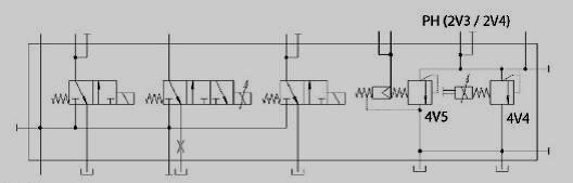
Pressure relief valve - 4V4 / Y004 coupler function


The coupler function valve (4V4) regulates the increase in hydrostatic pressure (PH) in proportion to the engine speed. Due to this component the coupler effect is simulated. The coupler function valve is fitted to the control block where the hydrostatic loop PH and tank return junction is located. If this junction is not closed, the pressure in the hydrostatic loop cannot increase, and the tractor does not reach its maximum pulling power. The junction between the hydrostatic loop PH and tank is closed by the coupler function valve (4V4). The coupler function valve is controlled by the electronic control unit. The strength of the current depends on the engine speed, and changes as shown by the following table :

  Engine speed in rpm        Current supplied at A                    Maximum PH in bar              Remark
               800                                    0                                        0                        Transmission at neutral
               800                          approx. 0.46                               78                        Transmission "active"
              1200                                1.23                                    105
         from 1400                             1.71                                     500

In order for the pressure to increase in the HP loop, it is necessary to maintain the electrical supply and the tightness of the coupler function valve. The tighness of the valve seal can be ensured by a mechanical lock mechanism.


Move the control lever 
Or tighten the internal Allen screw.

Pressure relief valve 4V5 - clutch function 
The clutch function valve is fitted to the control block where the PH hydrostatic loop and tank return junction is located. The clutch function valve also allows to limit the maximum pressure PH in the 500 bar (� 20 bar) hydrostatic loop. Due to the clutch function valve, when the clutch pedal is not activated, the junction between the hydrostatic loop and tank return is closed. By moving the clutch pedal, the clutch function valve opens and the hydrostatic loop communicates with the tank return channel. This results in a drop in pressure (interruption of the pulling effort) in the hydrostatic loop, proportional to how far in the clutch pedal is pressed (comparable to a mechanical forward clutch).
Clutch pedal pressed in fully, High pressure PH = 0 bar. The maximum pressure can be achieved in the hydrostatic loop only when the clutch valve (4V5) is functioning perfectly.


Checking the control block
If maximum pressure is not reached when measuring the HP pressure, the transmission module may be defective, but it is also possible that the internal seal tightness of the control block is the cause of the problem. To be sure that it is necessary to disassemble the transmission module, it is recommended to first check the seal tightness of the spool valve block (transmission control). The pressure in the hydrostatic loop can only increase if the pressure relief valve seals are tight.
- Coupler function (4V4 / Y004)
- Clutch function (4V5)
When the following conditions are met, the coupler function valve allows the pressure in the hydrostatic loop to increase :
- Engine speed higher than 1400 rpm (PWM - Signal)
- Limp home mode activated
- Valve locked mechanically (tighten the internal Allen screw or move the lever).
The clutch function valve is closed (increase in HP pressure possible) when the clutch pedal is not activated. The tightness of the 2 pressure relief valves (4V4 / 4V5) can be controlled by the T union. 


Remove the right-hand rear wheel and its protective guard located behind it
Remove the T union. Fit a test pressure gauge to measure pressures higher than 500 bar at the PH union.


Checking procedure :
Start the engine. Activate the limp home mode by pressing in the clutch pedal fully and pressing on the button.


Apply the handbrake. Use the limp home mode lever to start the transmission.


PH
T union
Possible causes
250 bar
No oil flow to the T union
Transmission module error (shuttle valve, pressure pipe union). Remove the module.
250 bar
Oil flows from the T union
Coupler function valve (4V4) or clutch function valve (4V5) not tightly sealed. Change the valve.


Checking the clutch function valve (4V4)


Mechanically lock the valve (tighten the internal Allen screw or move the lever

PH
T union
Possible causes
250 bar
Oil flows from the T union
Clutch function valve (4V5) not tightly sealed. Change the valve
250 bar
Oil flows from the T union, but the pressure is not constant
Electrically check the coupler function valve. Change the valve if faulty


DYNA VT hydraulic tests

Supply pressure measurements

Measuring points
Reference
on
component
Description
Measuring points
Reference
on
component
Description
M1
KV
Cooler upstream pressure
M11
ZWK
PTO clutch pressure
M2
SM
Lubricating pressure
M13
750
750 rpm PTO selector pressure
M3
AS
Flushing pressure
M14
VR
Front axle clutch pressure
M4
ES
Booster pressure
M15
DS
Differential lock pressure
M5
PU
Service pump pressure
M16
1000
1000 rpm PTO selector
pressure
M6
P
Transmission system pressure
M17
Brake service pressure
M7
I
Tortoise range shifting pressure
M18
Rear axle beam lubricating
pressure
M8
II
Hare range shifting pressure
M19
Reverse position HP pressure
M9
PH
High pressure (HP)
M21
Front PTO clutch pressure
M10
PHA
Rear axle beam and braking system pressure
M22
T
Oil leak on clutch function
spool valve / coupler function
solenoid valve


Precautions to be taken during the pressure measurements


The oil temperature must be between 35 and 45�C. When measuring the transmission pressure, raise all wheels of the tractor to prevent accidents.
Set transmission ratio (Hi/Lo) to speed of 0. Release the handbrake.
Engage the front axle. Differential lock and PTO clutch are not engaged. On right-hand side, in the middle of the tractor :
Remove right-hand rear wheel and its protective guard.
Connect a test pressure gauge. Measure the pressures set out below according to the different engine speeds.
- PU Pressure (M5). Pressure measuring point located between the service pump and the pressure filter.
- P Pressure (M6) System pressure downstream of pressure filter.
- ES booster pressure.
- AS flushing or discharge pressure
- SM transmission lubricating pressure.