Monday, 30 July 2012

Water Pump and Water Temperature Regulator - Remove and Install


Water Pump

Removal Procedure

Remove: 
- the fan and the fan pulley. Drain the coolant from the cooling system into a suitable container for storage or disposal. Loosen the hose clamps and remove the hose (not shown) from the water pump inlet.


1-front cover, 2-joint, 3-water pump, 4-setscrews, 5-joint, 6-cover, 7-setscrews

- the setscrews (4). The setscrews are three different lengths. Note the positions of the different setscrews.
- the water pump (3) from the front cover (1). If necessary, tap the water pump with a soft hammer in order to loosen the water pump.
- the joint (2). Discard the joint. If necessary, remove the cover (6) from the water pump. Follow Steps to remove the cover.
- the two setscrews (7).
- the cover (6).
- the joint (5). Discard the joint.

Installation Procedure

Ensure that the water pump is clean and free from wear or damage. If necessary, replace the water pump.


1-front cover, 2-joint, 3-water pump, 4-setscrews, 5-joint, 6-cover, 7-setscrews

If necessary, install the cover (6) to the water pump (3). Clean the joint face of the cover (6). Position a new joint (5) on the water pump (3).
Install: 
- the cover (6) to the water pump (3).
- the two setscrews (7) to the cover (6). Tighten the setscrews finger tight. Clean the joint face of the front cover (1).


- Tooling A in position (X). Use Tooling in order to align the new joint (2) to the front cover (1). 
- the joint to the front cover. Align the water pump (3) to Tooling. 
- the water pump to the front cover (1). Ensure that the gear of the water pump and the gear of the fuel injection pump mesh.
- the setscrews (4). Refer to Illustration. Tighten the setscrews finger tight. Ensure that all setscrews of different lengths are installed in the correct positions. Remove Tooling and install the two remaining setscrews (4).


Tighten the setscrews (4) and (7) in the sequence to a torque of 22 N�m (16 lb ft).
- the hose (not shown) to the water pump inlet. Tighten the hose clamps.
Fill the cooling system with coolant.
- the fan and the fan pulley.

Water Temperature Regulator

Removal Procedure

Drain the coolant from the cooling system to a level below the water temperature regulator, into a suitable container for storage or for disposal.
Loosen the hose clamps from the upper radiator hose and disconnect the upper radiator hose from the water temperature regulator housing (2).


Remove:
- the two setscrews (1) from the water temperature regulator housing (2).
- the water temperature regulator housing (2) from the cylinder head. Note the orientation of the water temperature regulator housing.


- the O-ring seal (3) from the water temperature regulator housing (2). Discard the O-ring seal.

Installation Procedure

Ensure that all components of the water temperature regulator housing (2) are clean and free of wear or damage. Check the water temperature regulator for correct operation.
If any components of the water temperature regulator housing are worn or damaged, the complete assembly must be replaced.

If the original water temperature regulator housing is installed, position a new O-ring seal (3) into the groove in the water temperature regulator housing (2). A new water temperature regulator housing is supplied with a new O-ring seal.
Install:
- the water temperature regulator housing (2) to the cylinder head. Ensure the correct orientation of the water temperature regulator housing.

- the setscrews (1). Tighten the setscrews (1) to a torque of 44 N�m (32.5 lb ft). Connect the upper radiator hose and tighten the hose clamps. Fill the cooling system to the correct level.

Engine Oil Relief Valve and Engine Oil Pump - Remove and Install


Engine Oil Relief Valve

Removal Procedure

Remove the engine oil pan. Keep all parts clean from contaminants. Contaminants may cause rapid wear and shortened component life.
Use an allen wrench to loosen the cap (1). Carefully remove the cap (1) from the housing of the engine oil pump (4).

Engine oil relief valve
1 � cap, 2 � spring, 3 � plunger, 4 - engine oil pump

The spring force will be released when the cap is removed.
Remove the spring (2) from the bore for the relief valve in the housing of the engine oil pump (4). Use long nose pliers to remove the plunger (3) from the bore for the relief valve in the housing of the engine oil pump (4).

Installation Procedure

Ensure that all components are clean and free from wear or damage. If necessary, replace any components that are worn or damaged. If the bore for the relief valve in the housing of the engine oil pump (4) is worn or damaged, the complete assembly of the engine oil pump must be replaced.
Lubricate the plunger (3) with clean engine oil. Use long nose pliers to install the plunger (3) and the spring (2) into the bore for the relief valve in the housing of the engine oil pump (4).

The plunger must slide freely in the bore for the relief valve.
Apply Tooling to the threads of the cap (1). Use an allen wrench to install the cap (1) to the engine oil pump (4). Tighten the cap to a torque of 21 N�m (15.5 lb ft).
inside the plunger and the cap. Ensure that Tooling (A) does not contaminate the bore for the relief valve in the housing of the engine oil pump.
Install the engine oil pan.

Engine Oil Pump

Removal Procedure

Remove:
- the engine oil pan. If the suction pipe has a support bracket, remove the support bracket. Note the position and orientation of the components for the support bracket.


1 - setscrews, 2 - suction pipe, 3 � setscrews, 4 - engine oil pump, 5 - pressure relief valve, 6 - head screws, 7 - front cover assembly, 8 - outer rotor, 9 � dowels


- the two setscrews (1) and the suction pipe (2).
- the joint (not shown) from the suction pipe. Discard the joint.
- the setscrews (3). Remove the assembly of the engine oil pump from the cylinder block.
If necessary, remove the pressure relief valve (5) from the housing of the engine oil pump (4). If necessary, remove the allen head screws (6) and the front cover assembly (7). 
- the outer rotor (8) from the housing of the engine oil pump (4). Do not remove the dowels (9) from the housing of the engine oil pump unless the dowels are damaged.


Installation Procedure

If necessary, install the pressure relief valve (5).
If necessary, lubricate the internal components for the assembly of the engine oil pump with clean engine oil. 
Install: 
- the outer rotor (8) and the front cover (7) to the housing of the engine oil pump (4). 
- the allen head screws (6). Tighten the allen head screws to a torque of 22 N�m (16 lb ft). Ensure that the two dowels (9) are correctly located in the housing of the engine oil pump (4). Position the assembly of the engine oil pump onto the cylinder block. Ensure that the dowels in the housing of the engine oil pump are aligned with the holes in the cylinder block.
-  the setscrews (3). Tighten the setscrews to a torque of 22 N�m (16 lb ft). Check the backlash between the idler gear (10) and the crankshaft gear.
- the suction pipe (2) and a new joint (not shown) to the assembly of the engine oil pump.
- the setscrews (1). Tighten the setscrews to a torque to 22 N�m (16 lb ft).
- the components of the support bracket. Ensure the correct location and orientation of the bracket and the retaining clip. Tighten the setscrews finger tight in order to align the components of the support bracket. Tighten the M10 setscrew to a torque of 44 N�m (32.5 lb ft). Tighten the M8 fasteners to a torque of 22 N�m (16 lb ft).
- the engine oil pan. 

Sunday, 29 July 2012

GPA20 differential - Adjusting the taper distance, install and shimming the pinion


Adjusting the taper distance

Check the components and replace those that are defective.
Using a press and a suitable fixture, Install the cone (30) fully onto the pinion shoulder.


Adjusting the taper distance

The taper distance must be adjusted before the pre-load shimming of the pinion bearings. The thickness of shims "E" (50) required to position the pinion is calculated according to the formula below:
E = Z + T - (X + Y)
E = 184.955 + T - (X +90.520).

Legend
Z Nominal pinion dimension = 184.955 mm
T Correction of the nominal dimension engraved on the end of the pinion; this may be a positive or a negative value.
X Dimension of the centre housing stamped on the rear right-hand side of the housing, behind the lift ram.
Y Dimension of the pinion with bearing = 90.520 mm.

Reinstall
Using a press and a suitable fixture, Install the bearing cone (31) fully onto the pinion shoulder.
Install the shims (50), their thickness determined by the above formula.
Lightly smear the external surface of the cup (37) with Loctite 603 or equivalent and Install it to make contact with the shims (50) using a suitable fixture. Eliminate all traces of Loctite. The cones and cups must be cleaned and lubricated after fitting. Install the pinion and the cup (33).

Preparing for pinion shimming
Determine a thickness of shims greater than the overhang dimension "a" on the cup (33) measured in relation to the housing face to obtain a provisional clearance of 0.10 mm to 0.15 mm maximum for the pre-load shimming that follows.


Screw two diametrically opposed guide studs onto the housing. Place the shims (36) determined during step and Install the thrust plate (35).
Install and tighten the screws (32) to 90 - 120 Nm after removing the studs.

Shimming the pinion

1st method: adjustment by preload
Place the dial gauge feeler pin on the end of the pinion.
Pull hard on the pinion through the front of the centre housing while turning it alternately from left to right in order to correctly "seat" the cones in the bearing cups. With the assistance of an operator, set the dial gauge to zero.
Depending on the clearance measured, select a definitive thickness of shims in order to obtain the following preload: P1 = 0.03 to 0.09 mm.
Take out the two diametrically opposed screws (32) and replace them with two guide studs. Remove the other two screws and the thrust plate (35).
Install the shims and reinstall the thrust plate.
Install the screws (32) lightly smeared with Loctite 270 or its equivalent and tighten to a torque of 90 - 120 Nm, having first removed the guide studs.

2nd method: torque adjustment
Remove or add shims (36) to obtain a pinion rotational torque of 0.80 to 2 Nm, measured using a Dial type torque wrench, with the pinion turning at approximately 1 to 5 rpm. Once the correct torque has been obtained, refit the screws (32) lightly smeared with Loctite 270 or equivalent, then tighten to a torque of 90 - 120 Nm.


Position the plug (41) in the housing, then refit the union (52) and the lubrication pipe clip nuts.

Reinstall and shimming the differential assembly

Reinstall the right-hand flange (25)
Carefully place the assembled differential in the housing. The right-hand flange (25) is assembled on the centre housing in a similar way to the left-hand flange (9). The positioning is ensured by the locating ring (45).

Reinstall the left-hand flange (9)
Remove the cup (14) and the deflector (13) from the flange (9).
Place the cup on the cone (17).
Install the tool ref. 3376847M91 on the housing, using two screws (56) tightened to a torque of 85 - 100 Nm.
Tighten the central screw to a torque of 10 Nm. Check that the ring gear is not restricted by the pinion and turn it several times to correctly "seat" the cones in the cups. Check the tightening torque of the tool central screw again.


Assemble and moderately tighten the hexagonal calibrated spacers "A" in the other two holes. Check that they are in contact with the housing.

Shimming
Carry out shimming to obtain: P2 = 0 to 0.25 mm.


Place a ruler edge against the two calibrated spacers.
Using a set of shims, measure the clearance "J" between the finger of the tool and the ruler "B".


Calculate the dimension "C" between the cup (14) and the mating face of the flange (9)C = (114 + J) � 70.


On flange (9), measure dimension "Y" using a depth gauge and a ruler.
Select the thickness "E" of the deflector (13) and shim (49) (if used) to obtain: E = P2 + (C - Y).


To carry out "P2" shimming, there are nine classes of deflector, each of a different thickness. If possible, shim to the maximum tolerance.
Remove the shimming tool and cup (14).
In flange (9), place deflector (13) and shim (49) (if used) and cup (14). The shim (49) (if used) must be fitted between the flange (9) and the deflector (13). Ensure the deflector is fitted in the right direction.


Reinstall the flange (9). Install the pipe (40). Check the backlash.

Adjusting and checking the backlash

- The backlash between the ring gear and the pinion ensures crownwheel and pinion reliability and correct operation of the assembly.
- This backlash must be checked or adjusted after:
� adjusting the taper distance
� shimming the differential unit.

Preparation
Remove the differential assembly.
Using a "standard" reversible flange extractor, remove the cup (27).


Pre-adjustment
Prepare a thickness of shims (38) of 0.30 mm.
- Do not take into consideration the DC (ring gear offset, e.g. -0.20) engraved on the external surface of the ring gear after the pairing number.
- The pre-adjustment can be followed by an adjustment at a later stage, if the backlash is incorrect during the final check.
Install the previously prepared shim(s) in the cavity of the half-unit (29). Lubricate and Install the cup (27)Reinstall and shim the differential assembly unit.

Checking the J2 backlash
J2 = 0.15 to 0.40 mm
Place the dial gauge feeler pin half-way along a ring gear tooth.
Check that the backlash is between 0.15 and 0.40 mm. Carry out this check on three points of the ring gear, at intervals of approx. 120�.
- If the backlash is incorrect, select and Install a new thickness of shim(s).
- Then offset the ring gear (23) in the desired direction, by increasing the value of the shims (38) and by reducing by the same amount the thickness of the deflector (13) or vice versa, in order to obtain the required backlash, without modifying the differential unit preload.


Reinstall the hand brake mechanism assembly. The plate (5) is rectangular. It must be positionedhorizontally, lengthways, so that the pin (6) is correctly positioned against the rod (13)Reinstall the gear (2) (if fitted) and the circlip (1).


Reinstall the left-hand cover plate. Install the hand brake control support, the proportional PTO support (if fitted on the cover plate), remove the guide studs, Install and tighten the screws to a torque of 72 - 96 Nm.
Position the control rod and adjust the hand brake mechanism.
Reinstall :
- the right-hand hydraulic cover plate.
- the intermediate shaft, the driving gear and the top link support.
- the linkage cover plate and the brake pistons.
- the left and right-hand trumpet housings.
- the stabiliser supports.
- the hitch hook.
- the wheels. Tighten to a torque of 400 - 450 Nm.

Reconnect the tractor between the gearbox and the rear axle.
Top up the oil level in the housings and check the level on the gauge located at the back of the rear axle. Remove the safety chocks. Reinstall the body (if removed). Start up. Bleed the main brakes and the trailer brake (if fitted). Carry out a road test. Check the correct operation of the controls and the electrical circuits. Check the tightness of the trumpet housing mating faces on the housing, the cover plates and the hydraulic unions.

Saturday, 28 July 2012

Differential of the GPA20 rear axle


The crown wheel and pinion, driven by the gearbox output shaft, drives the rear axle. The helical pinion is supported on either side of its teeth by two tapered roller bearings fitted in opposition. Lubrication of the bearing (30) (37) is ensured by a flow of transmission oil from the PTO top cover plate located at the rear of the tractor. The bearing cones are force fitted to the pinion and the rear cup, smeared with Loctite 603, is also force fitted in the rear axle housing. The front cup is free in its bore to allow for shimming of the pinion.
The ring gear is fixed to the differential unit by rivets. The differential assembly turns on two tapered roller bearings supported by two lateral flanges centred by rings and screwed to the rear axle housing. The differential assembly comprises two half-units holding two planet gears for models up to 75 hp and four planet gears for models whose power output exceeds 75 hp. The unit also holds two sun gears. The pinion is fitted in the rear axle housing. The crown wheel and pinion is adjusted using shims fitted between the centre housing and the bearing cup (37). The pre-loading of the tapered roller bearings (31) (33) and (30) (37) is obtained by shim(s) placed between the hand brake plate and the centre housing.
The pre-load shimming of the differential assembly is carried out by deflectors (13) of different thicknesses fitted behind the left-hand bearing cup (14). If needed, an additional shim (49) can be fitted between flange (9) and the deflector.

Differential lock
The left-hand flange contains the differential lock mechanism. The system consists of a piston and a mobile dog clutch splined with the left-hand trumpet housing input sun gear. The mobile dog clutch is moved by the piston which is supplied by the 17 bar hydraulic system via a solenoid valve fitted on the right-hand cover plate. The piston moves and pushes against the mobile dog clutch, compressing the spring. The teeth of the mobile dog clutch engage with a fixed dog clutch that is attached to the differential unit. In this position, the right and left-hand trumpet housing input sun gears turn at the same speed. When the pressure is released, the mobile dog clutch is driven back by the spring.
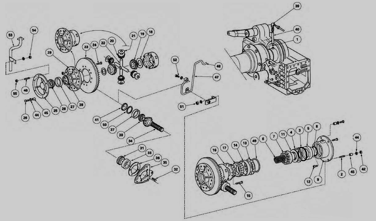
Parts list
(1) "O" ring (2) Stud (3) "O" ring (4) Circlip (5) Piston (6) Spring (7) Mobile dog clutch (8) "O" ring (9) Left-hand flange (10) Differential lock hydraulic assembly (11) Friction washer (12) Finger (13) Deflector (14) Bearing cup (15) Screw (16) Fixed dog clutch (17) Bearing cone (18) Washer
(19) Sun gear (20) Planet gears (21) Washer (22) Spider (23) Ring gear (24) Rivets (25) Right-hand flange (26) Screw (27) Bearing cup (28) Bearing cone (29) Unit (30) Bearing cone (31) Bearing cone (32) Screw
(33) Bearing cup (34) Pinion (35) Thrust plate (36) Shim(s) (37) Bearing cup (38) Shim(s) (39) Union (40) Differential lock supply pipe (41) Lubrication plug (42) Clip nut (differential support) (44) Washer
(45) Locating ring (differential support) (46) Stud (47) Pipe (48) Union (49) Shim(s) (50) Shim(s) (51) Nut (securing the lubrication pipe) (52) Lubricating union (53) Spool valve tank return pipe (54) Clip nut (55) Clip nut (differential support) (56) Screw

Removing the left-hand flange and differential lock assembly

It is possible to carry out maintenance on the differential lock hydraulic assembly (10) by removing only the left-hand trumpet housing.


Remove the left-hand trumpet housing.
Disconnect the supply pipe (2), unscrew the union (39) and take out the pipe (40). If access to the union (39) is difficult on tractors fitted with 4-speed economy PTO, remove the control (1)Remove the brake piston.

Special points
Purpose of the studs (2) and (46).
- Stud (2):
� this helps to attach the left-hand flange (9).
� it holds the lubrication pipe (47) for the pinion (34).


To reach the nut (3), remove the auxiliary spool valve support and work through the resulting opening. If this operation has to be carried out on a tractor fitted with 4-speed economy PTO, it is necessary to also remove the hitch hook support and the PTO top cover plate located at the rear of the tractor, the double gear and the control fork.
- Stud (46):
� this attaches the right-hand flange (25).
� it supports the return pipe (53) of the hydraulic spool valves.
The two studs (2) and (46) are fitted in the housing with a locking product (Loctite 242 or equivalent). The nuts on either side are tightened like the other screws holding the flanges, to a torque of 85 - 100 Nm.

Removal
Remove the flange (9), the locating ring (45), and if necessary, the friction washer (11), the mobile dog clutch (7) and the spring (6).

Disassembling and reassembling the differential lock assembly

Disassembly
Take out cup (14), deflector (13) and shim (49) (if fitted). Mark the deflector fitting direction and the location of the shim (49). Remove the circlip (4).


Take out the piston (5) using a jet of compressed air.
Remove the "O" rings (3) (8) (1). Unscrew the finger (12) (if necessary).

Reassembly
Check the components and replace those that are defective.
Clean finger (12), smear it with Loctite 542, then Install it and tighten it on flange (9).
Smear the "O" rings (3) (8) with miscible grease ("Amber Technical" or equivalent), and fit them correctly in the bottom of their respective grooves.


Using a plastic hammer, insert the piston (5) into the flange (9) while respecting the location of the finger (12).
Install the circlip (4), the shim (49) (if necessary), and the deflector (13), respecting its fitting direction, and the cup (14). The shim (49) (if used) must be fittedbetween the flange (9) and the deflector (13).


Reinstall the left-hand flange and the differential lock assembly

Install the "O" ring (1).
Assemble the washer (11), the mobile dog clutch (7) and the spring (6).
Reinstall the assembly in the left-hand flange (9).

Flange (9) fitting method. 


Screw two guide studs "G" (L = 60 mm approx.) onto the centre housing. Check for the presence of the ring (45)


Position the flange assembly (9) turning it so that the oil passage is facing downwards. Install the washer (44). Tighten alternately and uniformly the screw (56) and nut (42) to a torque of 85 - 100 Nm.
Install the pipe (40) and the union (39).

Sealing test
If maintenance has been carried out on the piston (5), seals (3) (8) or flange (9), it is necessary to check the sealing of the assembly.
Install a pressure gauge that has been previously tested for tightness to the supply union (39).


Supply the system with compressed air at approximately 5 bar to correctly place the piston and the "O" rings in the left-hand flange (9). Reduce the pressure to 0.3 bar and carry out the sealing test.
Close the valve. For approximately one minute, no drop in pressure should be observed on the pressure gauge.
Disconnect the pressure gauge and connect the supply pipe (2). If removed, reconnect the 4-speed economy PTO control and set the control.
Reinstall the brake piston and the left-hand trumpet housing.
Start the engine. Check the sealing of the supply pipe (2) and the correct operation of the differential lock.

Removing the differential assembly

Disconnect the tractor between the gearbox and the rear axle (the cab remains attached to the gearbox)Remove the wheels.
Separate the left and right-hand trumpet housings from the centre housing.
Remove the linkage cover plate.


Remove the hitch hook support. Remove the PTO top cover plate, the driving gear and the intermediate shaft. Take off the pipe (40).

Remove:
- the brake pistons. Carefully fit a sling to the differential assembly using a clamp.
Before working on the screws (56) and the nut (42). Loosen the screws (56) and the nut (42) alternately to gradually release the spring (6).
- the flange (9), the spring (6), the dog clutch (7) and the washer (11).
- the screws (26).
- the flange (25).
Take out the differential assembly from the centre housing.

Disassembling the differential assembly and the ring gear

Disassembling the differential assembly
Place the differential assembly on a workbench.
Extract the cones (17) (28) and cup (27), recover shims (38).
Mark the two half-units (29) with two joining paint lines. Remove the screws (15). Remove the fixed dog clutch (16). Separate the two half-units (29).


Remove the washers (18), the sun gears (19), the planet gears (20), the washers (21) and the spider (22). If the ring gear is replaced, the pinion must also be replaced. These components both bear the same number. They must be fitted as pairs. The ring gear and unit are originally assembled using rivets. During repairs, these rivets are replaced by screws and nuts.

Disassembling the ring gear 
Remove the ring gear from the unit.
Centre punch each rivet (24) (on the toothed side of the ring gear).
Using a 5 mm drill bit, drill the rivets to a depth of 10 mm.
Carry out a second drilling operation with a 12 mm drill to the same depth.
Drive out the rivets using a suitable pin punch.

Removing and disassembling the pinion

Remove:
- the right and left-hand hydraulic cover plate assembly.


- the circlip (1).
- the gear (2) (if fitted).
- the hand brake mechanism assembly.
- the screws (32), the thrust plate (35) and the shims (36).
- the cup (33) and the pinion complete with cones (30) and (31).
- the lubrication pipe (47). Remove and discard the plug (41), extract the cup (37) and recover the shims (50).

Disassembling the pinion
Extract the cones (30) (31).

Reassembling the ring gear and the differential assembly

Reassembling the ring gear
Check that the ring gear and pinion bear the same number.
Clean the mating faces of the new ring gear (23) and the unit (29) and the nuts and screws referenced in the spare parts catalogue.


Smear the first threads of the screws (1) with Loctite 270 and place them in the ring gear and unit. Tighten and lock the nuts (2) to a torque of 150 - 160 Nm.


Reassembling the differential assembly
Check the components and replace those that are defective.
Reassemble the differential assembly. 
Smear the screws (15) with Loctite 270 then tighten to a torque of 85 - 130 Nm. The clearance "J1" between the planet gears and the sun gears must be between 0.08 and 0.30 mm.
Insert the cones (17) (28) respectively in the bottom of the shoulder of the fixed dog clutch (16) and the right-hand flange (25), using a press and a suitable fixture. Place shim(s) (38) in the half-unit (29) to pre-adjust the backlash and then Install the cup (27).